« Posts tagged unreal

[Game] Unreal Engine 4 Architectural Rendering WIP 1

UE4 Architectural WIP 1

I took a look at the realistic rendering demo (https://www NULL.unrealengine NULL.com/blog/new-release-realistic-rendering-showcase) that Epic Games posted. It has fairly nice soft shadowing and pays close attention to how your eyes behave in light. I think the gap between pre-rendered and real time visuals is staring to get close enough that you could definitely use the Unreal 4 Engine for pre-visualizations and not have to visually take a gigantic hit. In fact you can probably produce more work at a faster pace using UE4. I’m building a small scene to create as realistic a render as I can using the new engine. No holds bared and no excuses. There’s going to be soft shadows, GI, ray traced light going through and off reflective and refractive surfaces plus caustic reflections! That is “literally all the things” when it comes to setting up great looking render. I’m going to be following the “PBR” rendering workflow so if you’ve never taken that challenge up this should be a good intro. There’s also a new PBR rendering contest going on now at Polycount (http://www NULL.polycount NULL.com/2014/06/14/petrolblood/). Here’s another great link to a Poly count forum thread (http://www NULL.polycount NULL.com/forum/showthread NULL.php?t=124683) that deals with PBR in games.

The shot you see here is a preliminary layout done in Maya with nearly all the rough models finished. The wall/ceiling moldings still have to be made. The next step is to take them into ZBrush. There I’m going to sculpt some more detail into some of the pieces and then use the retopology tools to lower the polygon count of each piece.
UE4 Architectural WIP 1 (http://www NULL.terrymatthes NULL.com/wp-content/uploads/2014/06/restaurant NULL.jpg)

[Game] Snowy Turn Table WIP 1

Freshly fallen snow on a grave

Hi guys and girls I just thought I would post a quick update on a collection of assets I’m creating for an upcoming iOS title. It’s a snowy scene and there are more meshes to come. I haven’t worked on cube map reflections yet, but I will soon. All meshes are built in Maya and ZBrush :)

Graveyard Shot Final

Windy Graves UDK

I’ve finished the UDK graveyard scene I was working on and started another :) This scene was fun to work on and it gave me a better understanding of the Unreal Engine as a whole. The most interesting part of the entire process was learning the UDK lighting system and how it handles (or doesn’t) BDRF in materials. For my next project I’m starting with a physically based shader that should make more sense coming from Maya. Putting together all the wind related meshes also taught me how far you can push cloth objects with simple skeletons and there will be more of that in my next piece.


Graveyard Scene WIP 1

Scene Snippet

Just before I left for Montreal I was able to snap some pics of my graveyard scene. I’ve got most of the modeling done, as well as the sky and rain systems. The Ivy on the foreground grave still needs to be skin weighted for wind movement, whereas the Ivy on the background grave is using a vertex offset to animate the ivy.

Scene Snippet (http://www NULL.terrymatthes NULL.com/wp-content/uploads/2013/06/SceneSnippet NULL.jpg)

I’m quite happy with the look of my high detail tree, but I still have to tweak the leaf cards a little as some of them don’t line up with the branches I’ve painted on the branch cards. Speaking of vertex weights the trees also need this. I’m going to use the same material wind network the grass uses so they move together. Painting up the trunk and branches in Zbrush was fun and eventually I saved out a surface noise setting for the bark so that I could apply the same look across the entire tree without having to sculpt each notch in the bark. This setting can also be loaded up for any other trees I might create to help things look consistent from tree to tree.

High Detail Tree for UDK (http://www NULL.terrymatthes NULL.com/wp-content/uploads/2013/06/mayaTree NULL.jpg)

Sky Material Network (http://www NULL.terrymatthes NULL.com/wp-content/uploads/2013/06/skysetup NULL.jpg)Vertex Ivy Material Network (http://www NULL.terrymatthes NULL.com/wp-content/uploads/2013/06/ivySetup NULL.jpg)Vertex Coloured Ivy (http://www NULL.terrymatthes NULL.com/wp-content/uploads/2013/06/vertexIvy NULL.jpg)Graveyard WIP paintover (http://www NULL.terrymatthes NULL.com/wp-content/uploads/2013/06/paintover NULL.jpg)The material networks are purposefully obscured as they aren’t final and I wouldn’t want anyone to follow them as they are not yet complete. When I’m done I’ll post a better breakdown of the these. I’ve also included a quick Maya shot of the foreground tomb’s ivy and it’s vertex weighting. The base of the leaves are black to keep them from shifting and the weight falls off to red towards the edges of the leaves. You don’t have to be too meticulous with the weights as you can manipulate them in the UDK treating them just like any other RGB value.

After all is said and done I think I’m the most excited about implementing torches on the fence in the background. I apologize for the crushed levels in the video. When I get back to Winnipeg I’ll re-compress it with adjusted settings. If you visit my Youtube (http://www NULL.youtube NULL.com/user/DelightningVFX/videos) channel you’ll see the pyre tests (http://www NULL.youtube NULL.com/watch?v=w2k-J_Bhme4) I’ve made in the past and I’m going to turn these into “flipbook textures” (video game GIFs) to be used in conjunction with particles to make a really believable torch. I’ll post more towards the end of next week.


Wish me luck fellas, I’m really happy with how everything is coming together and I can’t wait to show everyone the scene when it’s complete.

[Game] Game Trees WIP

Evegreen Trees Work In Progress

Evegreen Trees Work In Progress (http://www NULL.terrymatthes NULL.com/wp-content/uploads/2012/12/trees1 NULL.jpg)I’ve been watching people model trees all at work over the past few days and it’s driving me crazy. I must make a tree! So in keeping with my current project I’m going to sculpt an evergreen tree in the with snow on it for import into the Unreal Development Kit. The first thing I wanted to get done was the base mesh. I with the Speed Tree program that comes with the UDK. You can’t export from here but it does create the geometry in a pretty efficient way. After tooling around with settings for about an hour I was able to get a look I liked. Next I needed to recreate the same style of geometry in Maya. To get things started I began with the trunk. The trunk is pretty straight forward. It’s just a cylinder extruded along an ever-so crooked EP Curve. The next thing to do was create the branches. To save time you can model one branch and use Duplicate Special(Edit > Duplicate Special) to space a bunch of them along the +Y axis. This will not work properly unless your branch is pointing outwards from the center of your trunk with its pivot point also at that center of the trunk.

Use the Distance Tool (Create > Measurement Tool > Distance Tool) to get the  height of your tree. Divide your height by how many branches you want. Add that value to the Translate Y Offset. And don’t forget to also offset the Y rotation so the branches don’t space out in a straight row. Record (write down) your offset values as you’ll be using the same values to duplicate and space your “Fronds” or leaf cards. Your cards can be as simple or as complex as you want. Since I am just using this mesh as a guide in Zbrush I will keep my cards simple. I used a Bend Deformer ([Animation]Create Deformer > Non Linear > Bend) to curve a plane with 5 divisions in the height and only one in depth. I then tapered the sheet by selecting all the vertices at the end and scaling them together. You could stop modeling here and start texturing, but I want the poly count a lot lower. A Single tree as it stands is around 5000 vertices and unless you’re in a cinematic situation where you can control the poly count that’s just way to high for a tree. I think by taking this into Zbrush we can achieve a similar look at no more than 25% of the vertices. As added punishment I’m also going to push myself to use poly paint on this sculpt X_X

Terry

UDK Intro: Geometry Mode

Default 2D Scale Measurements for UDK 2D Platformer Kit

Introduction

You will have to recalculate the BSP every time you want to see the changes you have made.

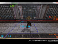
This lesson will cover the use of geometry mode to transform a brush’s shape, or create an entirely new brush. There are several different ways a brush can be manipulated in “geometry mode” .  Select your builder brush and then hit the geometry mode button (diagram 1).

Unreal Development Kit "Geometry Mode" Button (http://www NULL.terrymatthes NULL.com/wp-content/uploads/2011/07/BSP01_02 NULL.png)

Diagram 1: Geometry Mode Button

Basic Polygon Components (http://www NULL.terrymatthes NULL.com/wp-content/uploads/2011/07/BSP01_01 NULL.png)

Diagram 2: Polygon Components

If you are in geometry mode all corners of your builder brush will have turned into large red squares. When manipulating your brush you should keep the different components of a brush in mind (diagram 2). Using these components often and effectively will save you time. Lets change the position of our “Builder Brush” components using the transform tools. Start by making sure the geometry mode has been turned on.

Tools

Unreal Development Kit Geometry Tool Options (http://www NULL.terrymatthes NULL.com/wp-content/uploads/2011/07/BSP01_03 NULL.png)

Diagram 3: Geometry Tool Options

Edit
While in edit mode you can select and manipulate single or grouped vertices, edges and faces. Try selecting one of the vertices and then hold down CTRL and select a few more. There are no options in the “Properties” section (diagram 3) of the Geometry Tool for edit mode.

Extrude
This mode is available exclusively for manipulating the faces of your geometry. To access this mode you will first have to select a face that belongs to your brush. Only after doing this will the radio button become available.


(http://www NULL.terrymatthes NULL.com/wp-content/uploads/2011/07/bsp01_04 NULL.gif)
To extrude a face simply select the face you want to extrude and pull outwards on the coordinate handles. For a more precise extrusion you can enter the “Length” and “Segments” of your desired extrusion into the “Properties” section. A properly extruded face can be seen in diagram 4.


Don’t forget you can also affect the translate handles without pulling on them. Try using these commands:


  • translate X = LMB + CTRL
  • translate Y = RMB + CTRL
  • translate Z = LMB + RMB + CTRL
Unreal Development Kit Geometry Extrude (http://www NULL.terrymatthes NULL.com/wp-content/uploads/2011/07/BSP01_04 NULL.png)

Diagram 4: BSP Extrude Example

Brush Clip
Have you ever wanted to split a brush in two, or perhaps make two brushes from a single brush. If so the “Brush Clip” tool is just what you need. In the orthographic view port hold down the CTRL key and click with the RMB. You need two points that clearly cut across your brush to make the clip work (diagram5). Click “Apply” and you will notice that your brush has been split. You should also notice a line perpendicular to your clip line. This line is the “normal”.

Unreal Development Kit Brush Clip (http://www NULL.terrymatthes NULL.com/wp-content/uploads/2011/07/BSP01_05 NULL.png)

Diagram 5: BSP Clipping Example

The normal direction is changeable in the “Properties” section. Reversing the normal will reverse the cut. The normal has to be flipped before the cut is made to have any affect on the brush. Underneath “Flip Normal?” is the option “Split?”. This option will take the part of the brush that is usually clipped off and create a separate brush out of it .

Pen
The pen tool can create new brushes from points you lay down in a orthographic view. To create a brush connect three or more points ending at the first while holding down CTRL and clicking the RMB. The shape is set to auto extrude to a depth of 256.

Try connecting a punch of points together in a random shape. You will notice that the shape extrudes in the coordinate that matches its view. For an example of this create a shape in the top orthographic view and notice that it has been extruded along the Z axis. This extrusion will follow the world coordinate associated with the orthographic view you created it in.

In the “Settings” section you will notice several different options available to you. If “Auto extrude?” is turned off you will not get a default coordinate extrusion when you complete your pen path. The “Create Brush Shape?” option is used in conjunction with several features including the “Lathe” tool. When creating a shape you will notice that the editor always triangulates your shape. If this is something that you don’t want you can tick off the “Create Convex Polygons?” option and your new shapes will consist of quads and n-gons (diagram 6). Our last option is “Extrude Depth”. This is the default extrusion depth your pen tool will create when completed.

Regular vs. Convex Geometry (http://www NULL.terrymatthes NULL.com/wp-content/uploads/2011/07/BSP01_07 NULL.png)

Diagram 6: BSP Clipping Example

Lathe
The “Lathe” tool tries to take your shape and revolve it 360% around the dominant coordinate of your current orthographic window. The “Lathe” option can only be selected if you create a polygon with the “Pen” tool while the option “Create Brush Shape?” is turned on. Your shape will be green in colour.

The last two options will help to control how much of a 360% sweep your shape will occupy. The “Total Segments” option will set how many segments will make up the whole 360% turn. The “Segments” section will determine how many of those segments to actually produce.

Let’s make a simple square with the “Pen” tool and the “Auto Extrude?” option turned off. Start in the top orthographic view and make your four point selection (diagram 7). Now highlight the Y coordinate view (top right by default) and re-select your pen shape. In your options box set your “Total Segments” option to 16 and your “Segments” to 8. Now go ahead and lathe your selected shape.

You will notice that the inner radius of the lathe makes a semi circle. This is because our “Segments” option was set to half of our “Total Segments”.

Unreal Development Kit Lathe Example (http://www NULL.terrymatthes NULL.com/wp-content/uploads/2011/07/BSP01_08 NULL.png)

Diagram 7: BSP Lathe Example


Modifiers

Delete
Faces and verticies may be deleted using the “Delete” tool. Be careful when deleting. Look at your geometry closely and make sure you won’t get any unwanted shape changes from the deletion. Any faces you delete can always be repaired by using the “Create” modifier.

Create
Great for filling holes or bridging BSP the “Create” modifier works using verticies. Add a simple cube brush to the world and  delete one of it’s faces.Now select the four verticies around the open face in a clockwise fashion and then hit ENTER. The face will have been created with its normal direction facing outwards (diagram 8). If you were to make the same selection counter-clockwise the face will have been created pointing inwards.

Unreal Development Kit Create Face Example (http://www NULL.terrymatthes NULL.com/wp-content/uploads/2011/07/BSP01_09 NULL.png)

Diagram 8: BSP Create Face

Flip
That thing we just talked about called the normal; it’s what the “Flip” modifier is all about. Working on faces, the Flip modifier reverses normals. Reversing a face’s normals flips the side of the polygon that is rendered. This is why you can’t see the insides of meshes when you pass through them in spectator mode. The normal for all of those faces is pointing outwards.

Triangulate
Fairly self explanatory, “Triangulate” breaks mesh faces up into triangles (diagram 9). If you notice a surface of your BSP is rendering funny triangulate the faces giving your the trouble. Chances are they’re n-gons of some sort. Try creating a cube brush and selecting it’s top face. Now triangulate that face and notice how that quad (four edged  polygon) was broken up into two tris (three edged polygon).

Unreal Development Kit Geometry Mode Triangulation (http://www NULL.terrymatthes NULL.com/wp-content/uploads/2011/07/BSP01_10 NULL.png)

Diagram 9: BSP Triangulation

Turn
If you have two triangles on a brush that share a common edge you can “Turn” that edge .This rotates the the common edge of the triangles. Doing this causes the line that connects the two triangles to snap the the other 2 verticies that make up their 4 verticie border (diagram 10). If you still are unclear on this try using the pen tool to make a non extruded shape. Now “Triangulate” this shape and practice turning some border edges of triangles around.

Unreal Development Kit Turn Edge (http://www NULL.terrymatthes NULL.com/wp-content/uploads/2011/07/BSP01_11 NULL.png)

Diagram 10: BSP Turn Edge

Split
The “Split” tool adds “edge loops” or a series of verticies that run around your mesh connected by edges. Create a cube and select one of its edges and then use the Split modifier. Notice that a line was run around your shape that is perpendicular to the original edge you selected (diagram 11). This will always be the case when Splitting. In conjunction with the “Extrude” tool, splitting can work well to help you achieve whatever BSP shape you need. Diagram 13  illustrates the idea behind this.

Unreal Development Kit Edge Split (http://www NULL.terrymatthes NULL.com/wp-content/uploads/2011/07/BSP01_12 NULL.png)

Diagram 11: Edge Split BSP With Extrusion

Optimize
Using “Optimize” on a group of faces with adjacent edges will create a new polygon in their place that has no edges running though it. Any verticies that are no longer required to keep the shape of the brush will be deleted. Depending how you merge your faces you can end up with some really “interesting” polygons. Try to make sure all your optimizations create quads or tris.

Weld
Verticies can be merged using the “Weld” tool. The position of the resultant merge will be the location of the first verticie you selected (diagram12). Create a cube and select two of the top verticies and Weld them togeather. Now do the same to the other two and then once more so you’re left with one verticie. Move the single remaining top verticie to the middle of the cube in the top orthographic view. You know have a pyramid. Wasn’t that fun?

Unreal Development Kit Weld Vertex (http://www NULL.terrymatthes NULL.com/wp-content/uploads/2011/07/BSP01_13 NULL.png)

Diagram 12: Vertex Welding Steps


Conclusion

To exit geometry mode click the “camera mode” button (it looks like a TV camera) located beside the “geometry mode” button. It’s also of note that to “Undo” picked points with any of the tools you can hit the “ESC” key.

UDK Intro: Getting Started

Introduction

This lesson will cover the very basics of the interface while manipulating the “builder brush” with transform tools. For those of you who don’t have it yet the UDK can be downloaded here from Epic Games.

To enhance your transition into the Unreal Developer Kit please accept this assistance: Interface Diagram (http://www NULL.terrymatthes NULL.com/wp-content/uploads/2011/07/udk_interface NULL.jpg)

Startup

After you get UDK installed and running you will notice several different options in your windows start menu. For this lesson we are going to open the one labeled “Editor” (diagram 1) . A “Tip of The Day” window will greet you upon entry. Whether you choose to leave this notice on is up to you. Right now simply click the “OK” button.

Diagram 1: Unreal Development Kit Icon (http://www NULL.terrymatthes NULL.com/wp-content/uploads/2011/07/intro01_01 NULL.png)

Diagram 1: Unreal Development Kit Icon

Diagram 2: Unreal Development Kit SectionProgram Tabs (http://www NULL.terrymatthes NULL.com/wp-content/uploads/2011/07/intro01_02 NULL.png)

Diagram 2: Unreal Development Program Tabs

The first window to gain focus after clearing the Tip of The Day button is the “start page”(diagram2). This page is a way for Epic Games to get news and updates to you through the UDK. Close this windows and you should see the main program window behind it (diagram3).

Diagram 3: Unreal Development Kit Main Window (http://www NULL.terrymatthes NULL.com/wp-content/uploads/2011/07/intro01_03 NULL.png)

Diagram 3: Unreal Development Kit Main Window

The main program window is where we will be spending the remainder of this lesson. We’ll get to the other window, referred to as the “generic content browser” in the next lesson. Our first objective is to create a new file. There are two types of files we can create. Click on the File menu in the top left corner of the editor and select “New”.

We are given a choice between “additive” and “subtractive”. Generally you are going to want to use the additive level type. Select the additive radio button and click “OK”.

Navigation


Each view port can be maximized so that you can see its contents more clearly by pressing the “maximize view port button”. This button is the last button on the right of your view ports pictograph menu represented by a square with a black top border (see diagram 4). If you are running a dual monitor setup you might be interested in increasing your UDK screen space. To do this click the “tear of a floating copy” button located to the left of the maximize view port button. This button can be seen in diagram 4.

Diagram 4: Tear Off / Maximize World View Panel (http://www NULL.terrymatthes NULL.com/wp-content/uploads/2011/07/intro01_04 NULL.png)

Diagram 4: Tear Off / Maximize World View Panel

Perspective View Port
Translate back and forth by holding down the left mouse button (LMB) and moving your mouse forwards and backwards.

Pan the camera in any direction by holding the LMB and RMB down while moving the mouse.

Free look by holding down the RMB and moving the mouse around.

WASD Cluster
You can hold down the right mouse button and use the classic W,A,S,D key cluster to move around as well. The Q key and R keys can be used to change your camera’s elevation level.

Orthographic View Ports
You’ll have noticed by now that you have three other view ports available to you. These are your orthographic view ports. They are fixed camera views of your level from the top, front, and side. In these views you obviously can’t free look, but you can pan around and zoom.

Take note: if at anytime you feel the camera is moving to slow you can adjust the speed in each view port independently by pressing the “toggle camera speed button” seen here in diagram 5.

Diagram 5: Unreal Development Kit Camera Speed (http://www NULL.terrymatthes NULL.com/wp-content/uploads/2011/07/intro01_05 NULL.png)

Diagram 5: Unreal Development Kit Camera Speed

Basic Geometry Manipulation

On the left hand side of your screen you will notice two vertical rows of basic geometric shapes grouped together. This is your “brush pallet” (see diagram 6). Right click on the cube icon in your brush palette. A window with  the primitive’s properties will have popped up and in those properties we can clearly see the X, Y, and Z values for the cube’s dimensions. Click on each field and change the values to the following X:1024 Y:1024 Z:256. Now hit the “build” button and close the window. This red cube wire frame you have created is called a “builder brush” and it represents a shape that you could potentially add to your level. To get a better look at our new red “builder brush” lets navigate closer in the perspective view port.

Diagram 6: Unreal Development Kit Brush/Primitives Palette (http://www NULL.terrymatthes NULL.com/wp-content/uploads/2011/07/intro01_06 NULL.png)

Diagram 6: Unreal Development Kit Brush/Primitives Palette

This wire frame cube we have added can be manipulated just like geometry in a 3D suite such as Maya or Cinema 4D. You can manipulate geometry in  three basic ways: translate, rotate, and scale. All of the tools to do this can be found along with the “undo” and “redo” buttons in the pictograph menu just below the main program menu (see diagram 7).

Diagram 7: Unreal Development Kit Undo / Redo Buttons (http://www NULL.terrymatthes NULL.com/wp-content/uploads/2011/07/intro01_07 NULL.png)

Diagram 7: Unreal Development Kit Undo / Redo Buttons

The first button that looks like a mouse is your “selection” tool. If at anytime you lose focus of an object your manipulating you can simply select this tool and click on your object. You can’t manipulate geometry in this mode.

Translate
This button is located to the right of  “selection”. You can use this tool to move your object around in your level by clicking one, or combination of two axis arrows. The arrows are colour coded to match their coordinate direction. There is also a coordinate indicator in the bottom left of the perspective window (see diagram 8).

Diagram 8: Unreal Development Kit 3D Coordinate Orientation (http://www NULL.terrymatthes NULL.com/wp-content/uploads/2011/07/intro01_08 NULL.png)

Diagram 8: Unreal Development Kit 3D Coordinate Orientation

Rotate
To rotate your object you highlight one of the coordinate axis orbiting your object and drag. Unlike the translation tool you can’t move in more than one axis at a time.

Scale
Scaling your object can be done in two ways. You can scale your object up and down uniformly, or each coordinate direction can be scaled on it’s own.

To scale uniformly select the large gray square with the little square inside it. This is the bigger of the two gray squares seen side by side.  Notice that all coordinate axis handles are red. No matter which one you choose to pull on they will all scale your builder brush in the same fashion.

Non uniform scaling lets you increase the scale of one or two coordinates independent of the remaining coordinate(s) by dragging the handles you want to change. To select multiple handles move your mouse closer to the center of the two handles you want to manipulate.

Take note: You can use any of the manipulation tools as a selection tool. This way you don’t have to go  back and forth between manipulation tools and the selection tool.

Conclusion

The remaining intro lessons will be spent setting up very basic map. The goal will be to get you familiarized with the major aspects of the UDK. The topics you’ll be introduced to will include: adding geometry, materials, lighting, static meshes, particles, sound/music, and visually scripted events.

Icy Material

Introduction
Prerequisites

Creating Seamless Textures in Photoshop (http://www NULL.terrymatthes NULL.com/articles/seamless-textures-in-photoshop/)

Hi, thanks for stopping in. This lesson will be a basic introduction to creating a material for use inside the Unreal Development Kit. If you’ve never created a material from scratch before than this is a good place to start. Our final texture will be an ice sheet with a nice smooth finish.  The base for our material will be a photo we found off the internet. We will make this seamless (http://www NULL.terrymatthes NULL.com/articles/seamless-textures-in-photoshop/)and then us it as the base for our specularity, bump, and normal maps. To create the normal map for this texture we will be using CrazyBump (http://www NULL.crazybump NULL.com/). The most complex material nodes we touch upon are the reflection vector and the vector mask node to enable reflections in our ice. So now that you know what we’ll be doing let’s get started by looking at some examples of ice and snow I gathered from my favorite reference site CG Textures.com (http://www NULL.cgtextures NULL.com).

Reference

Ice Ground Reference (http://www NULL.terrymatthes NULL.com/wp-content/uploads/2010/12/m_101_icy_Reference2 NULL.jpg)

It’s always important to get good reference when building materials. Even if you are doing something cartoony great shots are about more than colour. Good reference tells you how the material acts. Ask yourself questions like: how does it reflect light? Are there any colour commonalities between all photos? Are some parts of the material giving of no specular highlights? My ice material is going to act as floor or wall material as it won’t be translucent. All of the ice in our reference looks patchy and that’s what I want. White is visible all the time as there is white noise all over these photos. These also all seem to be lit me a fairly bright source. You could have just grabbed any photo of ice and started looking at it for reference, but that’s not a good idea. You should think about the scale and the surrounding environment. Is this ice going to be seen far away, or close up? Ice looks really different at varied distances. If you took the properties of the middle shot and tried to use them for a floor in a fps game it might look odd. This is a really zoomed in shot of ice. If you were standing on top of it looking down you wouldn’t see close to that amount of detail. Especially the fine edge lighting on the cracks. So scale is important because It helps us to suspend belief. If the scale is off and the player notices they will immediately become disengaged and that’s no fun :( So decide how you want your ice to look and jump into Photoshop. We’re now going to setup the our material.

Photoshop

Within Photoshop we will create the diffuse, reflection, and specularity textures. We will be saving all of our images in the  Targa (TGA) format. Each channel in a TGA file has 8 bit’s of information. When you go to save a TGA in Photoshop you will get an option to select 24bit or 32 bit. Each colour of RGB is saved as one 8 bit channel. When you save a 32 bit Targa you get to include an extra channel. We will be using this feature to include our specularity texture in our diffuse file. I mention this because I don’t want you to just start saving files as 32 bit thinking they are better quality as there is no difference. From this point forward we want to be working in a new Photoshop file with a seamless texture as the base.
Diffuse and Specular maps (http://www NULL.terrymatthes NULL.com/wp-content/uploads/2010/12/m_101_icy_diffuse_spec NULL.png)

Diffuse Texture

Let’s Duplicate (ctrl+j) our base diffuse layer and remove it’s saturation by accessing Hue/Saturation (ctrl+u) and pull the saturation all the way to the left. This will make the layer gray scale. To create some variation in the light we are going to choose the Magic Wand tool from the menu and start making multiple selections (shift+mouse1) across the layer. We want to pick chunks of the texture out so we can change their brightness and contrast. When you have a selection you like go ahead and access the Brightness/Contrast under the image >adjustments menu. Let’s change the brightness and contrast so these selections stand out more than the rest. To help you see the adjustments you’re making better try Hiding Selection Border under the view>show menu. When you’re happy with your results Unselect (ctrl+d) your selection and go back into the Brightness/Contrast function. We want to lower the overall brightness and contrast of our specular map. If things are too bright they will shine too much and your material will look like a white sheet. The final step is to Select Everything (ctrl+a) on our specular layer and Copy (ctrl+c) it. Now we want to look at our documents “channels”. These are under the “Windows” menu in Photoshop. If you click on this you will see 4 different “layers” in a window labeled “Red”, “Green”, and “Blue”. They represent the colour information for your entire texture. Click the “new layer” button at the bottom of the panel to create a new channel. By default it will be labeled “Alpha”. Select this channel and Paste (ctrl+v) your specular layer into it. Now your specular map will be saved in your alpha channel. Click back on the layers window and make sure make sure your diffuse layer is the visible layer.  Now we will save the file using “save as” and select TGA as our file type. When you hit “save” Photoshop will give you the option to save as a 32 bit file. We need to do this or we will loose that specularity map sitting in our Alpha channel.

Reflective Texture

The reflective texture you use really depends on the environment you want to display your material in. For this example I don’t want a distinct reflection as much as I want a wash of colour to pass over the material. Find a picture you wish to use and paste it above your diffuse layer. Select your reflection layer and use Gaussian Blur (ctrl+alt+shift+g) to make any distinct forms unrecognizable. If you’re happy with your reflective texture go ahead and save it out as a 24 bit TGA. That’s 24 not 32. We don’t need that extra specular channel in this texture.

Crazy Bump

Normal and Reflection Maps (http://www NULL.terrymatthes NULL.com/wp-content/uploads/2010/12/m_101_icy_reflection_normal NULL.jpg)Normal Texture

If you haven’t installed CrazyBump get to to their website (http://www NULL.crazybump NULL.com) and download the free trial. When you’ve got the program up and running click the Folder button at the bottom left and choose the diffuse texture we saved out earlier. You will be presented with two choices after opening your file. The choices are just inverted height maps. Choose the one that best represents the contour of your diffuse material. When doing so remember that white is the high point and black is the low point. After choosing  you will be presented with a normal map and a set of sliders. These represent the different detail forms that will be present in your normal map texture. You want to move the sliders around until you get an accurate representation of your diffuse material form. When you’re finished click the save button and choose to save out only the normal map as a TGA. At this point it’s a good idea to copy this normal map into your Photoshop file containing the other maps. You always want to keep your assets for a single material in the same file. If you begin to run out of space, buy another HDD. Yes that’s right, you might have to spend some money. Who doesn’t like HDD shopping though? Honestly? If new computer parts don’t turn your “geek” on I’m curious as to why your reading a blog dedicated to video game technology tutorials. You’ve got “nerd” in you, it’s OK.

Unreal Development Kit

Setting Up Our Package

After launching the Unreal Development Kit Editor we want to open the content browser (ctrl+shift+f) and click the “Import” button at the bottom left of the content browser window. Now select all the files you want to import.  When you hit the “OK” button the UDK will start to import the textures one by one. For each texture you choose to import you have to set it’s import options in the dialogue box. The only thing I want you to keep an eye out for here is your normal map. When it comes time to choose it’s options change the “Compression Settings” from “TC_Default” to “TC_Normalmap”. Once complete you should be looking at a layout of all the textures you have imported. The last thing we want to do is go ahead and create a new material. To Do this right click in the empty space of your package and select “New Material”. An import dialogue box will appear again, but this time change the group name from “Texture” to “Material”. This will help keep your package organized. Now that you’re looking at your empty material we will start bringing our texture samples into it.

Unreal Development Kit Texture Import Options (http://www NULL.terrymatthes NULL.com/wp-content/uploads/2010/12/m_101_icy_importOptions NULL.jpg)Material Editor

To add a texture into our material we’ll first make sure it’s highlighted in the content browser then hold down the “t” key and click with our mouse in the empty space of our material. You will need to do this for each node so lets go ahead and finish that. Below is a picture of our final node network for our ice material. If you’re new to the material editor it might look a little scary, but don’t worry I’m going to explain the network one node grouping at a time as we build this material. One quick note before we start: You can view the output of almost every node by clicking it’s black box in the upper left hand corner. It’s a nice feature for troubleshooting.
Icy Material Network Unreal Development Kit (http://www NULL.terrymatthes NULL.com/wp-content/uploads/2010/12/m_101_icy_MatNetwork NULL.jpg)

Diffuse Input

Part 1: Reflection The diffuse input is going to contain the reflection for our material and since it’s the most complicated part of our network I’d like to do it fist and get it out of the way. There will be two parts to this group, the reflection and  a contrast boost added after the reflection has been mixed with the diffuse texture. To set up the reflection we are going to need four nodes. So lets grab them all and place them on our canvas. the fist node is one already here, it’s our reflection texture sample. The second is an “Add” node. Hold down the “a” key and click on the canvas to drop one down. This node can also be found under the “Math” section on right right hand tree menu. The third node is a “Reflection Vector”. Drop one of these down by holding the “r” key and clicking on the canvas. This node can also be found under the “Vectors” section. Our last node is called a “Component Mask”. This node will help us hook up the Reflection Vector to the UV input of our Reflection texture sample.

If you become lost just refer back to the diagram of the node network posted above. Our Reflection Vector output will plug into the input on our Component Mask. Next the Component Mask output will plug into the “UVs” of our Reflection Texture Sample. Plug the top tab of our Reflection Texture Sample output into one of the Add node inputs. The top tab of any Texture sample represents all three colour values as opposed to just red, green, blue, or alpha as the ones beneath it do. Finally drag the top output of our Diffuse Texture Sample into to the 2nd Add node input. Now marquee drag a box around this group while holding down ctrl+alt. When you let go right click in empty space and choose the “New Comment” option in your menu. This lets you add a comment box around your selection.

Part 2: Contrast Boost The contrast boost is just a “Power” node. You can use Power nodes to increase or decrease the contrast of a network. This node has two inputs. The first is the Base and the second is the Exp or exponent. Drag a Power node onto the canvas from the “Math” section in the right hand menu. For a base input we will plug the output of our Add node created above. As for our Exponent we will use a Vector1Constant (“1″+mouse 1). A Exponent value of 1 will not change the texture. Going down from one will decrease the contrast and (you guessed it) going up will increase the contrast.

Emissive Input

For the Emissive channel we will Copy (ctrl+c) our Diffuse Texture sample and Paste (ctrl+v) it next to our diffuse input. Now drag the RGB tab (top) output into the Emissive input of our material. There wasn’t that easy :)

Specular Input

We want to add some colour to our specular and to do this me need to multiply it by a colour value. Luckily we have nodes that do just that. Hold down the “m” key and click to drop down a” Multiply” node. Next hold down the “3” key and click to drop down a “Constant 3Vector” node. The three values of the Constant 3Vector node can be used to represent RGB and when you put those together you get a colour.  Plug the output of the Constant3Vector node into one of the inputs of the multiply. In the other Multiply input connect the white tab of our diffuse texture. This is where our specular texture was stored when we saved it as a 32bit Targa in Photoshop. Lastly plug the output of the Multiply node into the Specular input of the material. Don’t forget you can view what the result of the Multiply node will look like by clicking the black box in it’s upper left hand corner.

Specular Power

The specular power controls the size of the highlight that is cast on your material. There is no hard and fast rule for this number as your lighting is affected by all the different components that make up your material. What worked for my material may not work for yours. Hold down the “1” key on the keyboard and click to get a Constant1Vector on your canvas and plug this into the Specular Power input of the material.

Normal Input

The last grouping of nodes we have to put together is our Normal Input. Lets start by connecting the RGB tab of our Normal Texture Sample to the Normal input of our material. Now we are going to “bump” those normals of the surface of our texture a bit to give the ice a translucent look. If you go to your menu on the right and scroll to the “Utility” section you will see a node called “Bump Offset”. Drag this node onto your canvas. Now drag the Alpha(Specular) output of your Diffuse Texture Sample into the “Height” input of our Bump Offset node. Connect the output of the Bump Offset to the Normal Texture Sample’s UV’s and then connect the RGB output of the Normal Texture Sample into the Normal input of the material. Increasing the Bump Offset values give the illusion of surface depth which lets you “look into” the ice. At any time you can hold down the “l key” and drag your mouse over your material preview to drag a light around and get a better feeling for how your material behaves when lit.

Conclusion

Final Ice Material With Alternate Versions (http://www NULL.terrymatthes NULL.com/wp-content/uploads/2010/12/m_101_seamless_finaltotal NULL.jpg)I hope you had as much fun creating your ice texture as I did writing this tutorial. If your not happy with your outcome try again. The material I’m showing as my final was the fifth one I had created. A lot of creating materials is just getting a handle on all of the different settings and knowing what to expect when you combine different networks inside the material editor. If you have any questions email me or post them below. As always I’d love to see your work so post a link or drop me a line. Before I go I just wanted to show a couple other ice textures I created along the way.

Further Reading

Seamless Textures In Photoshop (http://www NULL.terrymatthes NULL.com/articles/seamless-textures-in-photoshop/)

Program Shortcuts Used

Photoshop
New Layer (ctrl+shift+n)
Duplicate Layer (ctrl+j)
Hue/Saturation (ctrl+u)
Burn (ctrl+shift+b)
Dodge (ctrl+shift+d)
Unselect (ctrl+d)
Select Everything (ctrl+a)
Gaussian Blur (ctrl+alt+shift+g)

Unreal Development Kit
open the content browser (ctrl+shift+f)
Copy A Node (ctrl+c)
Paste A Node(ctrl+v)
Add Node (a+mouse1)
Multiply Node (m+mouse1)
Vector1Constant (1+mouse1)
Reflection Vector (r+mouse1)