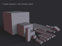
 (http://www NULL.terrymatthes NULL.com/wp-content/uploads/2012/12/tombscarf NULL.jpg)Since my last update I’ve added a cloth skeletal mesh to the scene. Cloth inside the Unreal Development Kit is something I’ve always wanted to take a look at. After watching a quick tutorial over at 3D Buzz (http://www NULL.3dbuzz NULL.com/vbforum/sv_showvideo NULL.php?v=3830) I was ready to start setting up my cloth in Maya. The video is good, but it skips the entire rigging process and starts with a pre rigged 3D plane brought into the UDK. I looked around on the internet for some Maya specific tutorials, but there weren’t any. The first thing that caught me while working this out was the use of the term “bone“. A lot of the tutorials instruct the reader to add two bones to the mesh. In Maya you don’t really lay down bones. You’re laying down “joints” and what I would consider the bones are the shapes Maya creates between those joints. Before you start you’re probably going to want to jump into Maya’s Animation tab so all the rigging tools are on your shelf. The first step in Maya is to place two joints in a chain along the X axis fairly close together. The next step after you’ve created these joints is to use a “smooth bind” to pair the joint chain with your mesh. That command is under the Animation Menu > Skin > Smooth Bind. Now with the joint chain bound to your mesh you can begin to “paint” your vertex weights. After being bound each joint in the chain stores a separate value for each vertex. Every individual vertex value lets the joint know how much influence it should have over that particular vertex. A value of 1 means the joint would act upon that vertex with 100% of it’s influence (or movement). A value of 0 means that the vertex will not follow that particular joint at all. Below I have a diagram showing how your joints should be setup and named. UDK will later ask us which bone we want associated with the cloth movement.
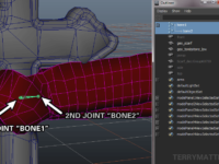
 (http://www NULL.terrymatthes NULL.com/wp-content/uploads/2012/12/bonesetup NULL.png)
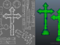
Now that the mesh is rigged go into “Object Mode” and use the right click menu to access the “Paint Skin Weights Tool“. Make sure you have textures enabled in your viewport when you’re doing this. You also have to be in the “Default Quality Rendering” mode under your perspective views “Panel” menu to see the weights change as you paint. The first joint “bone1” is going to be associated with all the parts of your cloth mesh you don’t want to move. For my scenario I have painted all the vertices of the knot white and all the vertices of the two scarf arms black. I do this because I don’t want the knot to move at all. I’ve included two diagrams below to show the weighting of my vertices to both bone1 and bone2. (http://www NULL.terrymatthes NULL.com/wp-content/uploads/2012/12/bone1 NULL.png)
 (http://www NULL.terrymatthes NULL.com/wp-content/uploads/2012/12/bone2 NULL.png) After you’ve weighted your vertices you can export the mesh as a FBX for import into the UDK. On import the UDK should recognize your mesh as a skeletal mesh and give you a different window type when it’s opened up through the UDK Content Browser. After import there are a few properties you need to activate in your mesh.
First you need to open up your cloth mesh in the content browser. You should now have the AnimSet Editor open. This is because UDK is treating our cloth as a “Skeletal Mesh“. The first property we want to activate is “Force CPU skining” this will tell the UDK that we want our mesh to be treated as a cloth. It’s found under the “Skeletal Mesh” roll out in the “Properties” pane. The second and final property we need to change is under the “Cloth” roll out. When there expand the “Cloth Bones” roll out and hit the green cross to add an entry to the Cloth Bones list. Now click in the name space for that entry and call it whatever you named the second joint in Maya. In my case it was “bone2”. With this done you’re now ready to place your mesh into your game scene. (http://www NULL.terrymatthes NULL.com/wp-content/uploads/2012/12/Scarf NULL.png)
Make sure your mesh is selected in your content browser and then right click in one of your views so that you may add your mesh to the scene. Once your mesh is in the scene you need to change a couple of it’s properties that we couldn’t access from the AnimSet Editor window earlier. Under the “Skeletal Mesh Actor” roll out there is a sub section called “Cloth” expand this. Under here we can  (http://www NULL.terrymatthes NULL.com/wp-content/uploads/2012/12/Scarf2 NULL.png)see the first option “Enable Cloth” and a lower option called “Cloth Awake On Startup“. Enable both these options. As an optional step you can play around with the wind values to try and get your mesh to receive a constant blowing force. To now see your cloth in action you can rebuild your map and launch the level, or simply right click in the perspective viewport and chose “Play From Here“. Cloth doesn’t animate in the viewport’s “Game Mode“.
That’s it for this Tombstone project. I hope anyone following along found some cool tips to help them get a little more out of the UDK.
Cheers,
Terry Matthes
 (http://www
 (http://www
 (http://www
 (http://www
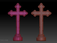
 (http://www
 (http://www
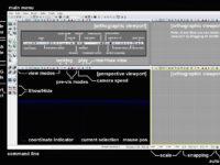
 (http://www
 (http://www
 (http://www
 (http://www
 (http://www
 (http://www
 (http://www
 (http://www
 (http://www
 (http://www
 (http://www
 (http://www
 (http://www
 (http://www
 (http://www
 (http://www
 (http://www
 (http://www
 (http://www
 (http://www
 (http://www
 (http://www
 (http://www
 (http://www