
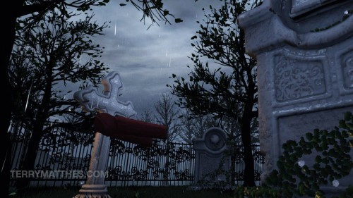
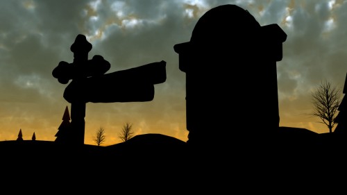
 (http://www NULL.terrymatthes NULL.com/wp-content/uploads/2013/03/windyplain NULL.jpg)Making grass move in the UDK isn’t overly complex but it does requite a decent handle on Maya and the Unreal Development Kit’s material editor. The concept at it’s core is to use the Material Property “world offset position” to make your grass wave. Control of the grass is split between three different systems: the “wind directional actor”, the material network we create for the grass, and our grass mesh’s vertex colours.
Maya
Our verdant journey starts here. I’m not going to go over modeling a grass plane, but if you have any trouble you can just take a look at the one I made here to see the relative complexity of the mesh.
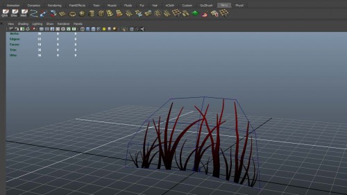 (http://www NULL.terrymatthes NULL.com/wp-content/uploads/2013/03/grassmesh NULL.jpg)
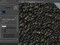
After you have created your planar mesh you’re going to need to jump into painting “vertex colours”. Vertex colours are literally just RGB values you’re painting on your mesh’s vertices through Maya’s vertex painting system. Before you go all nuts painting up your mesh you’re going to have to change a few of Maya’s options to ensure that vertex colours will appear properly in your viewport. The steps for enabling vertex painting can be found on Autodesk’s help site here (http://download NULL.autodesk NULL.com/us/maya/2010help/index NULL.html?url=Coloring_polygons_Make_vertex_colors_visible NULL.htm,topicNumber=d0e213327). After you get vertex colours working you can move on to the next step which is painting (http://download NULL.autodesk NULL.com/us/maya/2010help/index NULL.html?url=Coloring_polygons_Assign_colors_to_polygon_vertices_by_painting NULL.htm,topicNumber=d0e213575) a red gradient from the bottom of your mesh to the top. Lower red values will cause the vertex to be less affected by wind. Below I’ve placed a couple more grass planes along with the original.
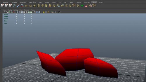 (http://www NULL.terrymatthes NULL.com/wp-content/uploads/2013/03/vertexColors NULL.jpg)
After your painting is complete you are ready to export your mesh for the UDK. You don’t have to do anything special on export in Maya to carry your vertex colours into the UDK just export your grass plain as a standard FBX.
Unreal Development Kit
Our mesh is done and it has all the properties it needs to accept directions from the “world offset position” in the material node we’re going to create. The first thing to do is start a new map and import your materials and models for your grass. After everything is imported create a new material.
In this material up with whatever diffuse, normal, and specular etc. that you need and then clear a fair amount of space in your material editor because node network we are going to create for wind is going to take up a bit of space.
Before we create the windy section of the material I wanted to break down the core of the wind network. I mentioned earlier we are using the “world offset position” attribute in our material to animate the grass. As you can imagine, feeding the world offset position a constant value would yield no animation. We need some way to animate the actual value we are sending to the world offset position.
To accomplish this we are going to use two nodes. The “Sine” node and the “Time” node. The time node will give us the changing value we need. Plugged into the sine node we can create a continually oscillating value between 0 and 1. This is the same principal I used to animate optical flares in my previous post (http://www NULL.terrymatthes NULL.com/unreal-2/materials/sprite-channel-controller/).
Next we need a way of incorporating the red values of our vertices to control the wind falloff on our grass mesh.
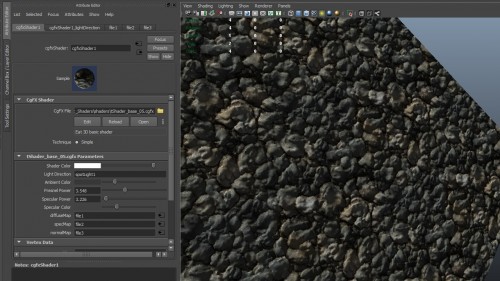
The wind instructions to affect the grass are going to come from a “Wind Direction” actor. Your going to need to put on in your scene and they are located in the classes hierarchy tab. When you bring up it’s properties you’ll see that there are a few different controls that we can use to affect the wind. Be sure to play around with these so you can get a good idea of how you’ve weighted your vertices after the network is complete. Beyond the diffue map, there isn’t anything in the network that you can’t grab directly from the right click menu in the material editor. Go ahead an copy the network below, then assign it to your mesh.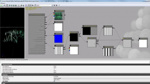 (http://www NULL.terrymatthes NULL.com/wp-content/uploads/2013/03/windyGrassNetwork NULL.jpg)
After updating your material network you should see the grass now waving at a constant rate in the wind. After this it’s up to you to discover some more interesting ways to make your grass move. Also take a minute or two and think about all the implications of this technique. There are a lot of things in video games you could apply this type of procedural animation to.
Conclusion
If you have more than one mesh that will use wind you should really look at setting up your material so it can be used for instancing. This material network can get large and loading it in for each plant is going to cause you some performance loss.
I hope this gave you a good understanding of wind principles and showed you a new way to spice up your Unreal Development Kit environments.
If you’re stuck on a particular step or want to know more about creating material instances ask away and I’ll do by best to help :)
 (http://www

 (http://www
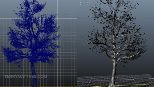 (http://www
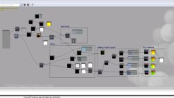 (http://www
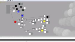 (http://www
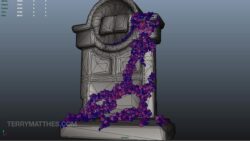 (http://www
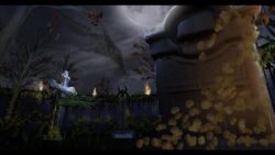 (http://www
 (http://www
 (http://www
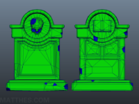
 (http://www
 (http://www
 (http://www