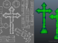
 (http://www NULL.terrymatthes NULL.com/wp-content/uploads/2012/11/tombstoneWIP4 NULL.jpg)Since my last update I’ve stopped working in ZBrush and started testing in the UDK. My goal for this update was to have the light maps working with a basic material in place. The first shot on the left shows the low poly tombstone with it’s UV’s layed out. These are also the same UV’s I used for the light map. If you plan your layout you can make sure that you use the same set of UV coordinates for both diffuse and light map.You still have to put the light map UVs in a second channel within Maya, but this can save you a lot of time. Making the UVs for the light map is a very similar process to making proper UVs for a normal map. You want to ensure that you have separated any faces that break out of the continuity of the surface flow. To illustrate this I have colored all of those faces blue. These faces happen to correspond to all the chips and scrapes in the model. These faces all have one thing in common. They are sharply opposing the direction of the faces around them. Faces like these have to be broken off from the model and separated into UV Islands. You’ve probably heard this term before. UV islands prevent normal map errors when baking down from your high res model to your low res mesh in programs like xNormal. A general rule of thumb is that if a face comes close to or is more than a 90 deg. angle from the regular surface flow it should be separated into it’s own island joined by any adjacent faces with the same behavior. The map pictured here is 1024 square. I should note that I left a little bit of padding around each UV group as this helps with normal and light maps.
 (http://www NULL.terrymatthes NULL.com/wp-content/uploads/2012/11/tombstoneWIP2b NULL.jpg)In the picture on the right you can tell the light maps are working correctly because the shadows in the second picture are falling over the crosses as they should. If there were errors in the light maps you might get strange blotches or shadows showing up on the wrong faces. Again it’s important that we separated all those sharply angled faces so that we don’t get these errors. It’s also of note that the lower the resolution of your texture, the more padding you need to give those islands. If they are too close the shadows will start to bleed from island to island. In the UDK the entire shadow maps are being baked down to very very low resolutions to save memory. If you look at the ground shadows they are set as high as you can go with 1 pixel of screen space being dedicated to 1 pixel in the light map. You can not do this for every asset in your map or you will kill the texture memory of your video card. I only did this as a test for myself to see how far I could push the shadow correctness. Now you might look at those shadows and think they aren’t that sharp, but in a game with a textured ground and movement they are more than enough to sell the realism of the shadow.
 (http://www NULL.terrymatthes NULL.com/wp-content/uploads/2012/11/tombstoneWIP3 NULL.jpg)Here we have a simple material with a diffuse, specular and normal map along with a 1 Variable Constant set to “10” being plugged into the specular power. To drop a constant down in your work area you can simply press 1, 2, or 3, on the keyboard and left click. Specular Power operates like Eccentricity on a Maya material. The higher you put the number the more “glossy” your highlight becomes. We are dealing with stone here so we’ve entered a low value of 10 as the porous nature of the stone surface would scatter a lot of the diffuse light being cast. The map we’ve used for the specular is actually a darkened version of the cavity map with some noise applied to help sell the diffuse nature of the stone surface. The cavity map works well as a specular base because it stops the cracks and depressions from casting light out into the scene and in turn sells the sunken nature of those areas. One last thing I wanted to touch on was your low poly mesh’s normals. I found that if I let the UDK set my vertex normals (which is does by default) my faces looked too sharp where the texture seams were running and I generally wasn’t happy with the result. I spent a bit of time setting all the normals in Maya and I wanted to use those instead. Luckily you can do this when importing.
 (http://www NULL.terrymatthes NULL.com/wp-content/uploads/2012/11/tombstoneWIP5 NULL.jpg)When you choose to import your mesh you can select a couple options that will stop the UDK from wiping out your normal values. Under the General section and Static Mesh sections there are two options; Import Tangents and Explicit Normals. Check both of these off. If you do all of this and your still having trouble with shadows falling improperly over your object you probably haven’t turned your light map settings up high enough in your mesh’s properties. If it’s the “ground” that isn’t showing shadows correctly then the same holds true for whatever surface the shadows fall onto. Remember though that with a static mesh you want a higher number for a crisper result and with BSP geometry it’s a lower number that casts a crisper shadow.
That’s all for now :) I’ll be back with more soon and hopefully have some of the actual scene to show. If anyone has any questions email me or just ask them in the comments section within this post.
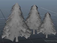
 (http://www NULL.terrymatthes NULL.com/wp-content/uploads/2012/12/trees1 NULL.jpg)I’ve been watching people model trees all at work over the past few days and it’s driving me crazy. I must make a tree! So in keeping with my current project I’m going to sculpt an evergreen tree in the with snow on it for import into the Unreal Development Kit. The first thing I wanted to get done was the base mesh. I with the Speed Tree program that comes with the UDK. You can’t export from here but it does create the geometry in a pretty efficient way. After tooling around with settings for about an hour I was able to get a look I liked. Next I needed to recreate the same style of geometry in Maya. To get things started I began with the trunk. The trunk is pretty straight forward. It’s just a cylinder extruded along an ever-so crooked EP Curve. The next thing to do was create the branches. To save time you can model one branch and use Duplicate Special(Edit > Duplicate Special) to space a bunch of them along the +Y axis. This will not work properly unless your branch is pointing outwards from the center of your trunk with its pivot point also at that center of the trunk.
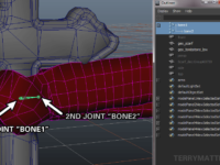
 (http://www
 (http://www
 (http://www
 (http://www
 (http://www
 (http://www
 (http://www
 (http://www
 (http://www
 (http://www
 (http://www
 (http://www
 (http://www
 (http://www
 (http://www
 (http://www
 (http://www
 (http://www
 (http://www
 (http://www